It can be seen from the above evolution that the processing technology of the crankshaft is developing in the direction of high speed, high efficiency and compounding. At present, the more popular roughing process is the car-car pull process and high-speed outer milling of the main journal, the high-speed follow-up milling of the connecting rod neck, all adopt dry cutting; the finishing is processed by CNC grinding machine, with automatic feeding and automatic Correct the grinding wheel, automatic compensation of size and roundness, automatic indexing and electronic synchronous drive at both ends. The main journal and the connecting rod neck can be completely ground in one clamping; the super finishing machine uses a CNC belt polishing machine with a size control device. CNC High Speed ​​Follower Milling (Fig. 4): The performance of a high speed servo milling machine model VDF 315 OM-4 is now presented. The machine tool is a flexible CNC milling machine designed and manufactured by BOEHRINGER of Germany for the crankshaft of automobile engine. The machine uses the workpiece rotary and milling cutter feed servo linkage control technology, which can clamp the crankshaft without changing the crankshaft rotation center. Rod journal. It adopts integrated composite structure bed, electronically synchronous rotary drive at both ends of the workpiece, featuring dry cutting, high machining precision and high cutting efficiency; using SIEMENS 840D CNC control system, equipment operation manual on the man-machine interface, through input parts The basic parameters can automatically generate the machining program. It can process various crankshafts with a length of 450-700mm and a rotary diameter of 380mm. The diameter of the connecting rod journal diameter is ±0.02mm. CNC car-car pull machine : This equipment can complete all concentric turning in one setting, and complete the car-car pull (vehicle side end face) processing on the same machine tool, with high processing efficiency, through the use of special chuck and tool system. It can also realize flexible processing, and the maintenance of the machine tool is simple and the maintenance cost is also low. It is especially suitable for the crankshaft where the side of the balance block does not need to be processed and the journal has an undercut groove. The broaching process can be replaced by a high-efficiency comb (Fig. 5) turning process. The combing process is usually carried out at the last step of the process, and high-speed finishing is achieved by a small amount of radial feed and longitudinal turning. From the several advanced equipments introduced above, we can see that one thing in common is high-speed and high-efficiency flexible, which is suitable for the development trend of many varieties and small batches of today's products. Since crankshaft machining is different from ordinary machining, many processes must use special tools, such as the internal milling, car-car pull and high-speed outer milling described above, all of which use special tools. The cutters are complex and cost-effective. More expensive. If the product variant involves changes in the crankshaft structure, the new tool body must be used to machine the crankshaft, which affects the product development cycle and manufacturing costs, and ultimately leads to a lack of competitiveness. Tool manufacturers such as Walter have now developed flexible tools for the manufacture of crankshafts – modular (Figure 8). The product development cycle is greatly shortened and the manufacturing cost is reduced. At present, the domestic car crankshaft production line is mostly high-speed flexible production line FTL (Flexible Transfer Line). This production line is characterized by not only processing the same series of crankshafts, but also processing variant products, replacement products and new products, which are truly flexible. In order to further improve the production efficiency of the high-speed flexible production line and adapt to the market faster, the next step of FTL development is the Agile Flexible Transfer Line (AFTL). Its main purpose is to: Due to the special structure of the engine crankshaft, the author believes that the crankshaft AFTL should have the following characteristics: it consists of a high-speed machining center and a high-efficiency special machine tool (including a small number of combined machine tools). The machine tools are arranged according to the process flow and connected by automatic conveyors, using flexible fixtures and efficient special tools. In order to prevent the failure of key process equipment and cause the whole line to be discontinued, parallel equipment can be added to meet the needs of mass production. The following is the process flow (metal processing only): Milling end face, fixed total length, drill quality center hole, car size end outer circle→milling spindle neck and shoulder shoulder→milling connecting rod neck and shoulder shoulder→carriage main journal and sinking groove→car pull connecting rod neck and sinking groove→gun Drill hole → cleaning → fillet rolling → flange drilling tapping → fine grinding spindle neck (CBN) → fine grinding rod neck (CBN) → oblique cutting small end → oblique cutting flange end → rolling Thrust surface, milling keyway → dynamic balance → abrasive belt polishing spindle, connecting rod and flange outer diameter → cleaning, cooling → detection classification. Several questions about the above process flow are discussed as follows: Doosan Main Wiring Harness,Doosan Main Pump Assy,Doosan Excavator Main Pump,Doosan Loader Parts JINING SHANTE SONGZHENG CONSTRUCTION MACHINERY CO.LTD , https://www.sdkomatsudozerparts.com Evolution of crankshaft machining process
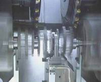
Figure 1 Double cutter car - car pull 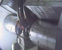
Figure 2 Double cutter high speed milling
High-speed grinding of CBN developed in the 1990s. The crankshaft grinding machine produced by LANDIS in the United Kingdom has a grinding speed of up to 120 m/s. It takes only a few minutes to complete the grinding from the blank to the fine grinding with the suede method. This will lead to a new situation in which grinding replaces other roughing processes. 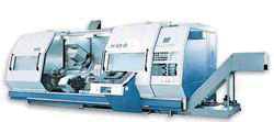
Figure 3 M40G turning and milling composite machining center Introduction to the performance of typical crankshaft machining advanced equipment
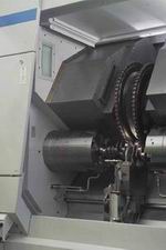
Figure 4 CNC high speed follower milling machine 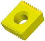
Figure 5 comb blade 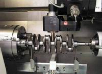
Figure 6 Pushing surface fine car rolling machine 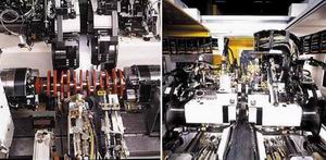
Figure 7 Front and rear shape of the JUCRANK 6000/50-50 CBN grinding machine 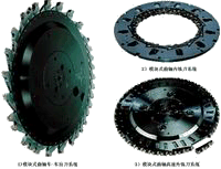
Figure 8 Modular Crankshaft Tooling System Discussion on the Program of Crankshaft Agile Flexible Production Line (AFTL)
Progress in crankshaft manufacturing technology and preliminary exploration of agile flexible production line
